CNC MILING SIMPLE CURVES
Simple curves are those that consist of whole or part circles, where the start point, end point, centre and radius of each arc or circle are known.
The G2 command moves the Controlled Point clockwise around an arc.
The G3 command moves the Controlled Point anticlockwise around an arc.
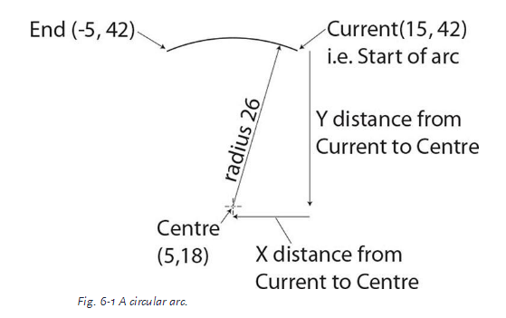
The format of both commands is the same: specify the X, Y and Z values at the end of the arc, and the X and Y distances from the current (start) point to the cen- tre of the arc. Because X, Y and Z values represent the end of the arc, the letters I and J are used for the X and Y distances from the current (start) point to the centre of the arc, and a suitable command for the path shown in Fig. 6-1 would be: G3 X-5
Y42 Z10 I-10 J-24, which makes the Controlled Point travel anticlockwise in an arc
from the current point (15, 42) to X-5 Y42 Z10.
From the current (start) point to the centre of the arc (5, 18) is:
Xcentre – Xcentre (5 − 15 = −10)
so I−10 specifies the required distance along the X axis.
Ycentre – Ycentre is 18 − 42 = −24 so J−24
specifies the required distance along the Y axis.
The Z height will change from the current Z to the end Z as the Controlled Point
moves from the start of the arc to the end.