CNC milling Controlled Point
the Controlled Point, the axes of movement, and coordinate systems; homing and touching off.
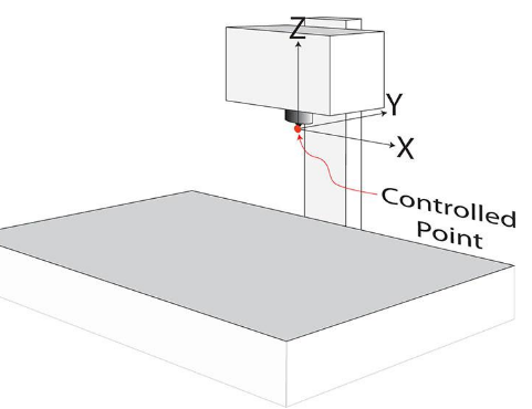
CNC software moves a Controlled Point in relation to the workpiece as it carries out a machining sequence. The Controlled Point may be anywhere, but is normally a reference point at the end of the tool, on the same axis as the spindle, as shown in Fig. 2-1.
It does not matter whether the head moves or the slides move, the software will always act as though it is moving the Controlled Point. It is best to focus on what happens to the Controlled Point, so what really matters is not the way the parts of the machine move, but the way the Controlled Point moves in relation to the work.
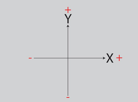
Looking directly down on to the table, the XY plane is parallel to the flat surface of the table, with the X axis running left to right and the Y axis running front to back (Fig. 2-2). The origin is the point where the X and Y axes cross and both axes have a value of zero at that point.
On the X axis, the X value becomes more positive as the Controlled Point moves to the right in relation to the table, and more negative (or just less positive) as the Controlled Point moves to the left. The Y value becomes more positive as the Controlled Point moves to the rear.
The Z axis runs vertically up and down at right angles to the XY plane (the table) and represents the vertical movement of the Controlled Point. The Z value be- comes more positive as the Controlled Point moves further away from the table. For a ‘tabletop’ vertical milling machine, in which the head moves up and down and the table is fixed to the cabinet or bench, Fig. 2-3 shows the orientation of the axes for movements parallel to the X axis (left and right), the Y axis (forwards and backwards) and the Z axis (vertically up and down).