CNC milling CAD program
Computer-generated models are often generated by connecting or intersecting
basic geometric objects such as cubes and cylinders. For example, you can model
a hole by intersecting an object with a second, cylindrical object. This type of func-
tion is a standard feature of every CAD program, while different CAD applications

vary in the number and sophistication of the additional features they offer.
CAD applications include guide functionality to draw lines that are not part of
the workpiece itself. These help the designer to position or orientate the various
parts of the workpiece. For example, if you want the four holes shown in figure 1.26
to lie within a circle with a diameter of 27.5 mm, you need to define the center of
each hole. The blue lines in the diagram are the guides used to do this. It is this
type of functionality, along with system integration and built-in industry standards,
that make CAD software so complex and expensive.
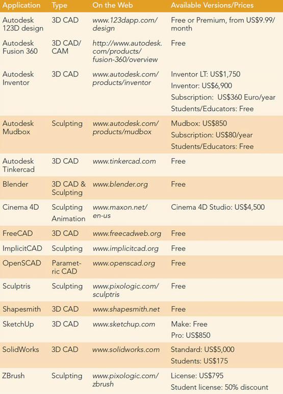
Alongside traditional 2D and 3D CAD models, milling models for components
such as threads can also be constructed using parametric (i.e., mathematical)
methods. Recently, digital sculpting techniques developed by the movie and video
gaming industries have begun to be used for industrial modeling. Digital sculpting
enables free-form modeling on a digital basis. The basic technique uses custom
software tools to smooth, flatten, and drag basic shapes into the required form.
Many of today’s CAD applications offer all three modeling options, enabling
you to combine traditional construction plans and mechanical functionality with
artistic design elements. Curves and arches are extremely difficult to produce using
conventional design tools, and machining the results nearly always requires 3D
milling using at least four axes.