Using Optical Edge Finder work origin on CNC milling
Optical edge finders, or machine scopes, are like microscopes for machine tools (Fig. 2-15). The scope is held in the spindle and the operator looks through the eye- piece. The scope has a lens that looks vertically down and it carries cross hairs so that the axis of the spindle can be aligned with an edge, a hole or a mark on a work- piece. In use, it is focused on the work by raising or lowering the Z axis, and the scope shown is in focus when it is 50mm above the surface of the workpiece. The X and Y axes are jogged until the edge or other feature of the workpiece is aligned with the cross hairs (Fig. 2-16). The axes can be touched off at that point. For a rectangular workpiece, the X axis is touched off by aligning the cross hairs with the left face and then the Y axis is homed by aligning the cross hairs with the front face.
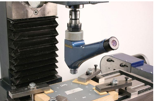
Fig. 2-17 shows the cross hairs aligned with the centre of a hole. There is some judgement required in this case, so an alternative is to move the slides so that the cross hairs are aligned with one edge of the hole and touch off there, then move in the same direction to align the cross hairs with the opposite edge of the hole and note the distance as shown on the axis read-out of the CNC program. Halve that distance. Move the slide back to a position well before the first edge of the hole, then forwards to that half-distance point (Fig. 2-18). Touch off again at that point. The movement backwards is designed to counter any backlash in the slide move- ment so that the various points are approached from the same side, in the same direction. Repeating this sequence for the other axis results in the centre of the
hole being at (0, 0). This same sequence of taking half the distance from one edge to another is the basis of movements often used with a probe, as we will see later.