TECHNIQUES FOR CNC MILLING SETTING THE WORK ORIGIN
How you set the work origin depends to a large extent on how accurately it needs to be set for any particular job. It also depends on the features of the CNC software being used. If, for example, a small finished object is to be produced by cutting it from a large sheet, there will be enough leeway in the waste around the finished object for a simple pointer, aligned by sight, to be sufficiently accurate for identifying a posi- tion where the origin could be located. If, however, an object is to have additional machining done in a precise relationship with other existing faces or features, aligning by sight is unlikely to be sufficiently accurate and more sophisticated
methods must be used to locate the origin.
Using a Wiggler
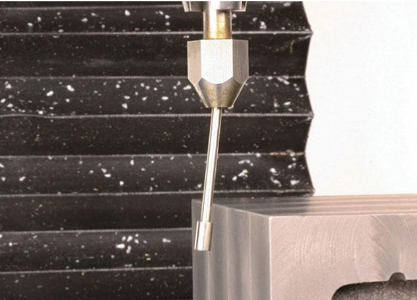
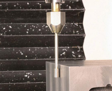
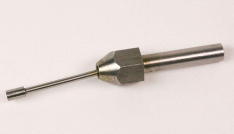
A wiggler is a simple device, consisting of a body and a probe arm, used to locate the vertical faces of a workpiece (Fig. 2-10). The probe arm is attached to a ball that sits inside the body so that the arm can move laterally. The outer end of the arm carries a ball or a cylinder of known diameter.
To touch off the X axis, the probe should be located to the left of the left edge of the workpiece and movements should take place along the X axis. The probe is held in the spindle and rotates with the spindle at a low speed (say 500rpm), the end wobbling about as it does so. Moving the Controlled Point so that the outer end of the arm is slowly brought into contact with the leftmost face of the work- piece makes the outer end run in a more circular path until it is finally concentric with the axis of the spindle, such that the end turns but does not wobble. Advanc- ing the Controlled Point further in the same direction makes the arm flick out of alignment and run along the face of the object, visually indicating that the Con- trolled Point has passed the point at which the arm can rotate concentrically (Figs 2-11, 2-12 and 2-13 show this sequence). At that moment, the Controlled Point is half the diameter of the end of the arm away from the face of the workpiece. If the arm carries a 6mm (¼in) diameter cylinder, the Controlled Point will be 3mm (1/8in) away from the face. Because the probe is to the left of the intended work origin, it will be at a negative X coordinate, i.e. −3mm or −0.125 in.