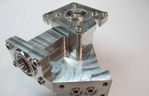
CNC Milling Quality
Even if the pattern itself appears simple, it is a challenge to mill with certain mate- rials. To keep the text looking clean, you have to use the smallest possible end mill. Because we used a circular mill, the vertical inner edges of the cuts in the finished piece all have rounded radii. A 1 mm mill produces curves with a radius of 0.5 mm. To keep the work as simple as possible, we used a plot file and WinPC-NC instead of more complex CAM software.
To keep things as simple as possible, we chose a relatively simple pattern cre- ated using a plot file. However, this approach isn’t ideal and produced some rather strange passes in the course of the job. For example, the curves of the letter “b” have two obvious edges that aren’t part of the original model. These are not milling errors, but rather errors that occurred during the conversion of the plot file to G-code.
This chapter doesn’t aim to produce super-precise milling results, but rather to explain which tools and parameters you can use to produce satisfactory re- sults with a range of materials. Even if your machine control software has built- in CAM functionality, it is always preferable to use a dedicated CAM application whenever possible.
Wherever possible, we milled the pattern using an initial pass at a depth of 1.5 mm followed by a second 0.5 mm pass. The results shown in the illustrations are not digitally processed in any way and the workpieces aren’t completely freed of chips and dust.
Cutting Parameters Some of the required spindle speeds and feed rates are not available using a Stepcraft-2/600 and a Kress 800 FME spindle. However, the values quoted in the course of this chapter are all more or less suited for use with this or similar machines. The photos indicate the degree of accuracy you can expect from the quoted settings, and don’t be afraid to conduct your own experiments!
